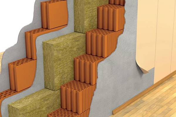
These types of panels are made of two thin mental pages (of steel or aluminum) with an elastic insulation. The main idea behind these panels is the system of mass – spring – mass so that the insulation substance between two pages will pose the role of spring and correspondingly it makes the sound energy to go away.
 It must be noticed that the middle insulation must not be connected to thesteel pages or be adhered to them because it establish a kind of sound bridge which prevent the insulation from proper acoustic function. There are four parameters which has important role in theperformance assessment of two layer panel which are the followings:
- Resistance against air flow
From the acoustical point of view, resistance to air flow for porous materials is vitally important. Resistance to an air follow with the speed of v in a panel with the thickness of t can be computed by the measuring of the rate of air pressure (pressure drop per unit time-δP) after the air passes the panel:
Airflow Resistance R = δP / v (Pa/m)
By dividing the resistance of air flow on the panel thickness, specific resistance to air flow is extracted and it is not depended to the thickness of insulation.
Airflow Resistivity r = R / t Pa/m2
Specific resistance to air flow will rise linearly with the increase of density. Incidentally, considering the above relation it can be deducted that Specific resistance to air flow will also rise with the decrease of thickness, which might seem impossible at the first thought. However this deduction for insulation substance it perfectly logical and it means that insulation substance with less thickness will result in the same pressure drop, and consequently its resistance to air flow is bigger. Acoustical properties of fibrous and porous insulation is very much depended to air flow resistance. If the air flow resistance of rock wool is so much, sound will rebound and if it is little, sound will pass the insulation without any absorption.
- Resonant frequency
Two layers panels will show a very favorable sound reduction coefficient when their frequency is more than resonant frequency.
 The opposite plot shows the sound reduction coefficient of a specific panel (composed of 2 layers of metal pages and Rock wool) in different frequencies. As one can see, after the resonant frequency (f0) the values of sound reduction coefficient have risen step-like. The straight line of lower limit is the indicator of a one layer panel which is the simplest tools of sound insulation. Two layers panel for frequencies upper than f0 has obvious advantages. Therefore, as the frequency of a two layer panel is lower, the value of sound reduction coefficient will rise, in a wider frequency range, and the acoustical performance of panel will be better as well. So as to calculate the resonant frequency of two layer panel, there is below approximate relation: Where m1 and m2 are surface density and d is the panel thickness. One can notice that as the surface density increase, the resonate frequency will decrease and consequently the acoustical performance of a two layer panel will improve.
- Density
In principal, the increase of porous materials’ density like rock wools’ density will cause the increase of resistance to air flow, and accordingly soundproofing features of this insulation will improve.
- The Diameter and Direction of fibers
With the purpose of acoustic insulation, it is better to employ rock wool with parallel fibers.
Duct insulation
These below notifications can be useful in the time of duct insulation:
-Employing devices with the least sound intensity
-Keeping the exhaust valves as far as possible from sensitive places to sounds
-exhaust valves must have a distance from goosenecks at least 1.5 time as big as the biggest rectangular duct; for circular duct this distance must be at least 1.5 time as long as the duct’s diameter
-Curve-like goosenecks is recommended to be used, however, using them with sharp edges is not recommended
-If curve-like goosenecks is not fit for the structure, it is better to use elbow chamfer bearing
-It is better to reduce the speed of air exhausting- it can be achieve by increasing the duct size
-Duct angle must not be alterable more than 15 degree – under the circumstances a gooseneck with the above specification must be used
-Reducer (the reducer of duct size) must not have more than 45 degree angle and increaser must not have more than 60 degree angle – specification of Reducer or increaser is done accordingly to the direction of air flow.
Escape noise
Escape noise is a noise which escape duct. Rectangular ducts allow these phenomena to happen more than circular ducts. Especially for lower frequencies escape noise happens more often. Break-in noise is another concern which penetrates from the Duct wall. Then again, rectangular duct allow break-in noise to happen more than circular ducts. All in all, if the duct is to be implanted adjacent to tumultuous equipment, it is better to use acoustic cover in order to prevent penetration of noises.
The role of frequency in noise reduction
In general, lower frequencies are absorbed hardly more in comparison with higher frequencies and they have a lower pressure drop as well. The thicker acoustic cover a duct have the better sound absorption for the lower frequencies it shows. The usage of silencer in order to absorb sound with middle and high frequencies will be effective enough.
To select proper silencer the below factors must be in mind
- Sound absorption coefficient – the quantity of sound reduction after the implantation of silencer
- Static pressure drop of air flow in the time of air flowing from silencer
- Reproduced noise – the produced sound due to the flowing of air from silencer (Proportional to the static pressure drop)


